
Foodservice design isn't just a specialty consultant required to get through a health department, it is an art form where the foodservice designer is the artist, the building envelope is the canvas, and the building plans they create are their art. Every foodservice designer has their own unique style. They even have their own vocabulary. The plans they create are the design and they guide the construction of the kitchen.
A foodservice designer's style is a compilation of their life experiences and the lessons they learned along the way
Their designs are never identical and they never stop improving their process. They couldn't stop if they wanted to. Foodservice design is a wide and ever-changing medium guided by architectural trends and innovative new technology. As foodservice designers finish projects and gain experience they inevitably gain insight into their design flaws. They then inject this insight back into their building plans as notes and details to prevent the next project from the issues of the past. This feedback loop is a core tenet of foodservice design, it is also the main reason that no two foodservice designers are alike. Simply put, a foodservice designer's style is a compilation of their life experiences and the lessons they learned along the way.
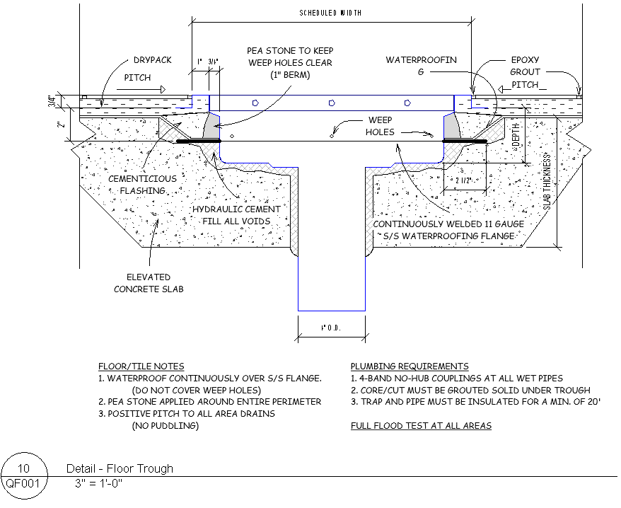
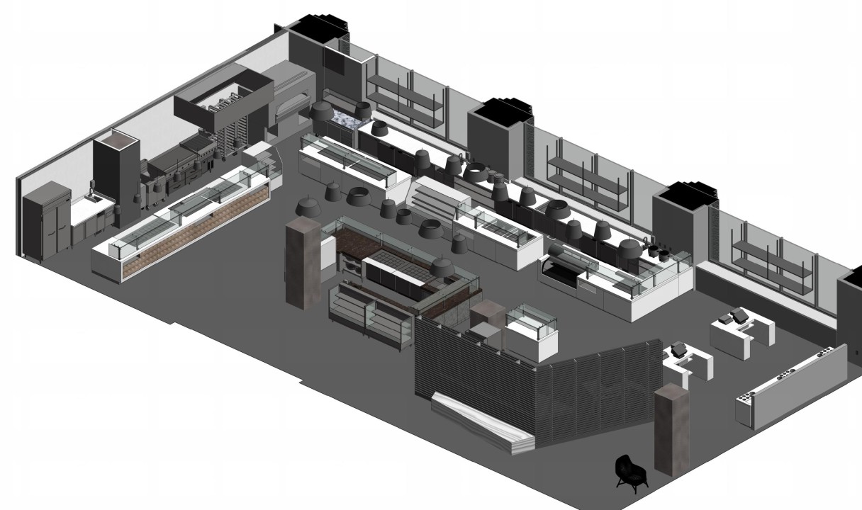
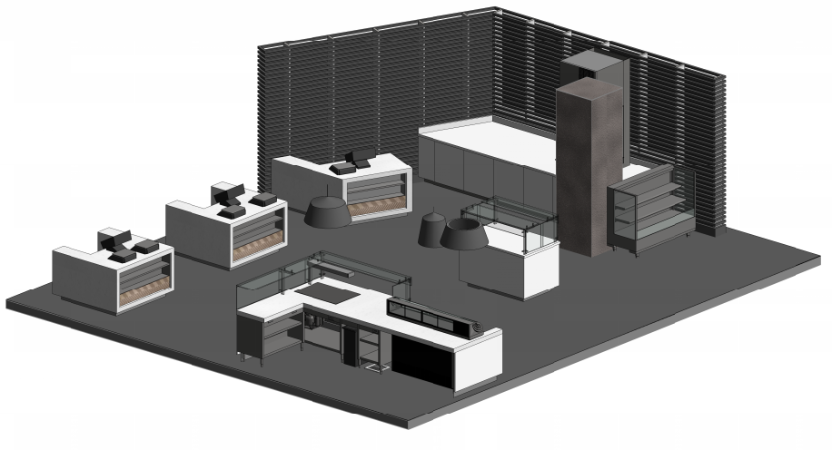
In the foodservice world, a single set of construction plans contains lines, symbols, notes, details, schedules and legends that together form the design and layout of each piece of kitchen equipment. While the layout is important, these plans also become the user manual for how to engineer and construct this particular kitchen. They touch every trade in the construction process because the foodservice equipment demands it. Some examples of foodservice engineering that you will find in almost every set of foodservice plans are electrical outlets, plumbing valves, floor sinks, mechanical exhaust ductwork, refrigeration lines, beverage conduits, wall backing, and slab depressions. These days it is not uncommon for foodservice design to also include color 3D isometric views that also show electrical outlets and plumbing valves. These 3D color views are perfect for explaining their one-off creations to the eyes of the reader who can range from the architect, engineer, contractor, electrician, plumber, chef, restaurateur, and even the health department.
The result of a creative professional with so many variables is a plethora of different approaches to foodservice design drawings; some based on perfecting foodservice construction methods, others based on showing off the skill and artistic value of the designer, and some based on passing the burden of liability onto others. Passing liability may seem negligent but in construction liability is a fine line between what needs to be done and how to do it, and it's up to the foodservice designer to determine their individual risk and reward. Some foodservice designers will take the risk of telling subcontractors exactly how to build something with the expectation that they receive the reward of a proper installation. Others may decide to let the subcontractors provide the means and methods as long as the finish line is the same. Inevitably all foodservice designs are a combination of all of the above approaches but still conform to two trains of thought when it comes to the electrical, plumbing and mechanical portion of their designs; either they create rough-ins drawings or they create connection point drawings.
Rough-Ins
Rough-in is just the term used for the first stage of the installation process, the other stage being the final connection. Foodservice equipment requires water and dedicated electric to be brought within 36" of the equipment, typically located in the closest wall behind the equipment.
These locations, or suggested installation points, are typically referred to as rough-ins and are provided by some foodservice designers that offer rough-in drawings.
When they are still able to access the inside of these walls, the electricians and plumbers will run their wires and pipes to junction boxes and pipe hangers located behind each piece of equipment. These locations, or suggested installation points, are typically referred to as rough-ins and are provided by some foodservice designers that offer rough-in drawings. Each junction box is referred to as an electrical rough-in and each water or drain location is referred to as a plumbing rough-in.
-1.png?width=799&name=0%20(2)-1.png)
Rough-in drawings will typically include dimensions from the floor and walls to provide the electricians and plumbers with exact locations for each rough-in. Sometimes rough-in drawings will also show the location on the equipment where each rough-in needs to connect to, this is referred to as the connection point.
Connections Points
After the rough-ins are installed and inspected, walls are closed up and finished and the foodservice equipment can be delivered. At this point the electricians and plumbers must finish the installation by making the final connections. Each piece of foodservice equipment has a specific location where the electrical and plumbing must be connected and these locations are referred to as connection points.
-1.png?width=354&name=0%20(3)-1.png)
Connection point drawings show these locations with itemized tags for every piece of equipment along with a itemized table that provides each piece of equipment's utility requirements.
-1.png?width=1243&name=0%20(4)-1.png)
The itemized tables, or schedules, are created for both rough-in drawings and connection point drawings and there are only minor differences between a schedule for rough-in plans and a schedule for connection point plans. For example, rough-in schedules contain rough-in heights, whereas connection point schedules contain connection heights.
Each piece of foodservice equipment has a specific location where the electrical and plumbing must be connected and these locations are referred to as connection points.
Once the equipment is delivered, the electricians and plumbers begin the process of making the final connections by connecting the rough-ins to the connection points on the equipment. When these connections are made on the jobsite by subcontractors they are referred to as field wiring and field piping. When these connections are made in the factory by the manufacturer they are referred to as factory wiring and factory piping. Once the field wiring and field piping connections are made, the installation is completed and the kitchen is ready for final inspections.
Want to test out rough-ins and connection points for yourself? Get started with a FREE trial of KitchDesigner.
